Full-Screen Image Format
The IBM Enhanced Graphics Adapter (EGA) supported a number of display modes, but all of the graphics in the game were shown in mode 0Dh. This was a 320x200 mode that permitted up to 16 distinct colors on the screen at any one time. 320 × 200 = 64,000 pixels, and log2 16 = 4 bits, meaning one complete screenful of graphics required 256,000 bits or 32,000 bytes to store.
There are several 32,000-byte full-screen images housed in the group files. These images are drawn on the screen to present pre-title, title, ending, or other information to the player:
| Entry Name | Description |
|---|---|
| BONUS.MNI | “Bonus Stage - Get Ready!” screen, shown before a bonus level begins. |
| CREDIT.MNI | Credits screen, accessible via the main menu. |
| END*.MNI | End story screens, shown upon finishing an episode. |
| ONEMOMNT.MNI | “One Moment” screen, shown when a new game begins. |
| PRETITLE.MNI | “Apogee Software Productions Presents - Cosmo’s Cosmic Adventure” screen, shown when the program first starts. |
| TITLE*.MNI | Title screens, shown before the main menu. |
Full-screen images are not used within the game world; only the menus and interstitial areas between levels use these types of images.
Colors and Palettes
Images on a computer display are comprised of three primary colors – red, green, and blue (RGB). Turn them all on and it’s white, turn them all off and it’s black. Between full-on and full-off, some amount of depth is provided to allow the exact levels of each of the three RGB channels to be specified (most displays nowadays provide at least 256 different levels on each channel). No matter what final color is desired, some mixture of RGB channel levels will reproduce it.
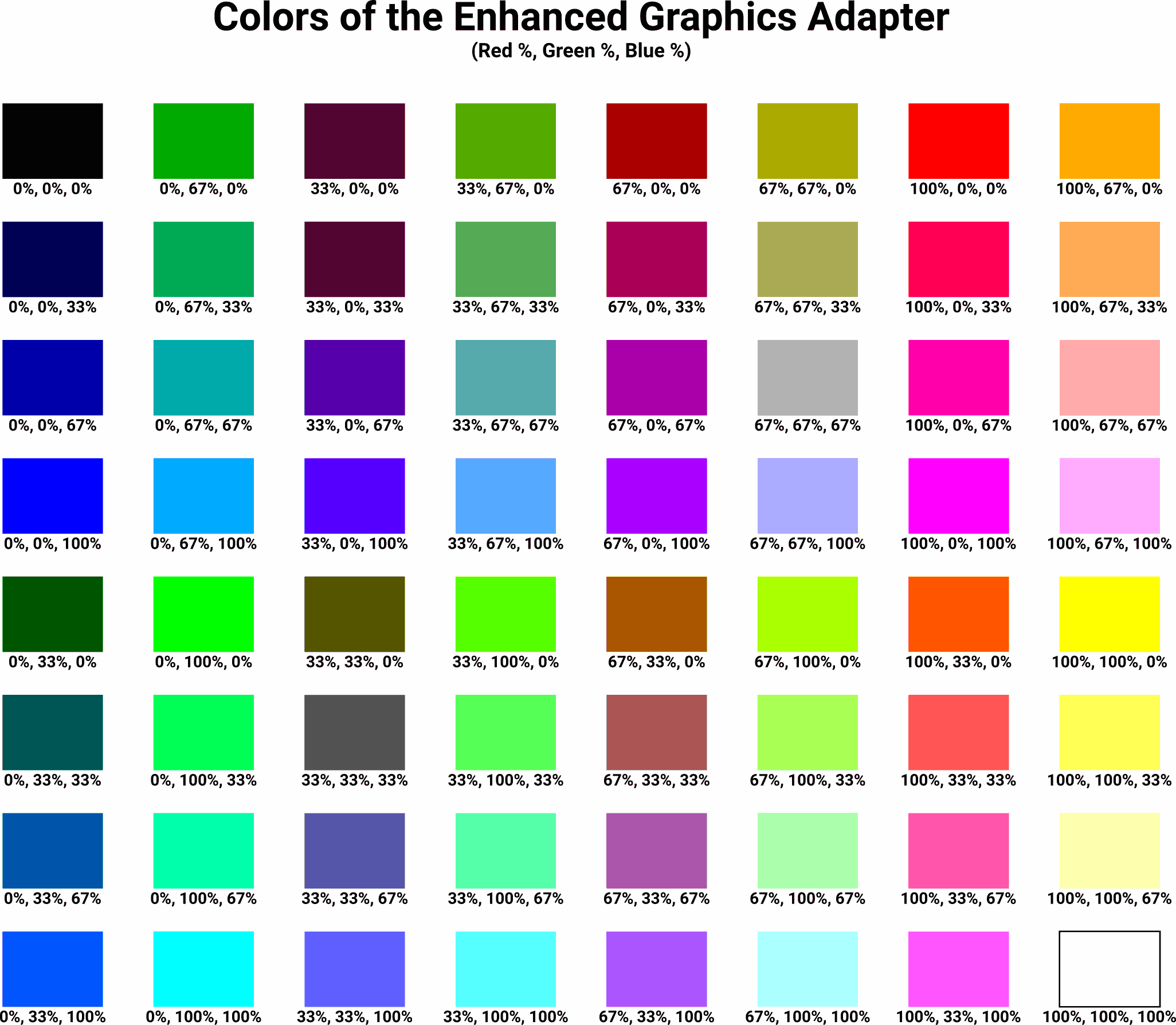
EGA displays, on the other hand, supported just four levels per RGB channel. This limited the number of distinct reproducible colors to 64 (4³):
Natively exposing 64 colors to the software would have required six bits (log2 64) per pixel, and six is an unusual number, so IBM adopted a color palette to reduce the number of necessary bits to four. This reduction in bit count meant that software would be restricted to just 16 colors at any one time, but it was free to choose which of the 64 colors were included in its palette.
The four bits that comprise each pixel of the image data, both on disk and in video memory, are just a palette index number – the value by itself doesn’t convey any color information until it has been looked up through the palette. A palette could be created with 16 shades of blue-green, or only bright pastel colors, or whatever the programmer wanted. There was not even a requirement that the palette colors be unique – a palette containing 16 values that all resolve to black is perfectly valid, and would happily display as such.
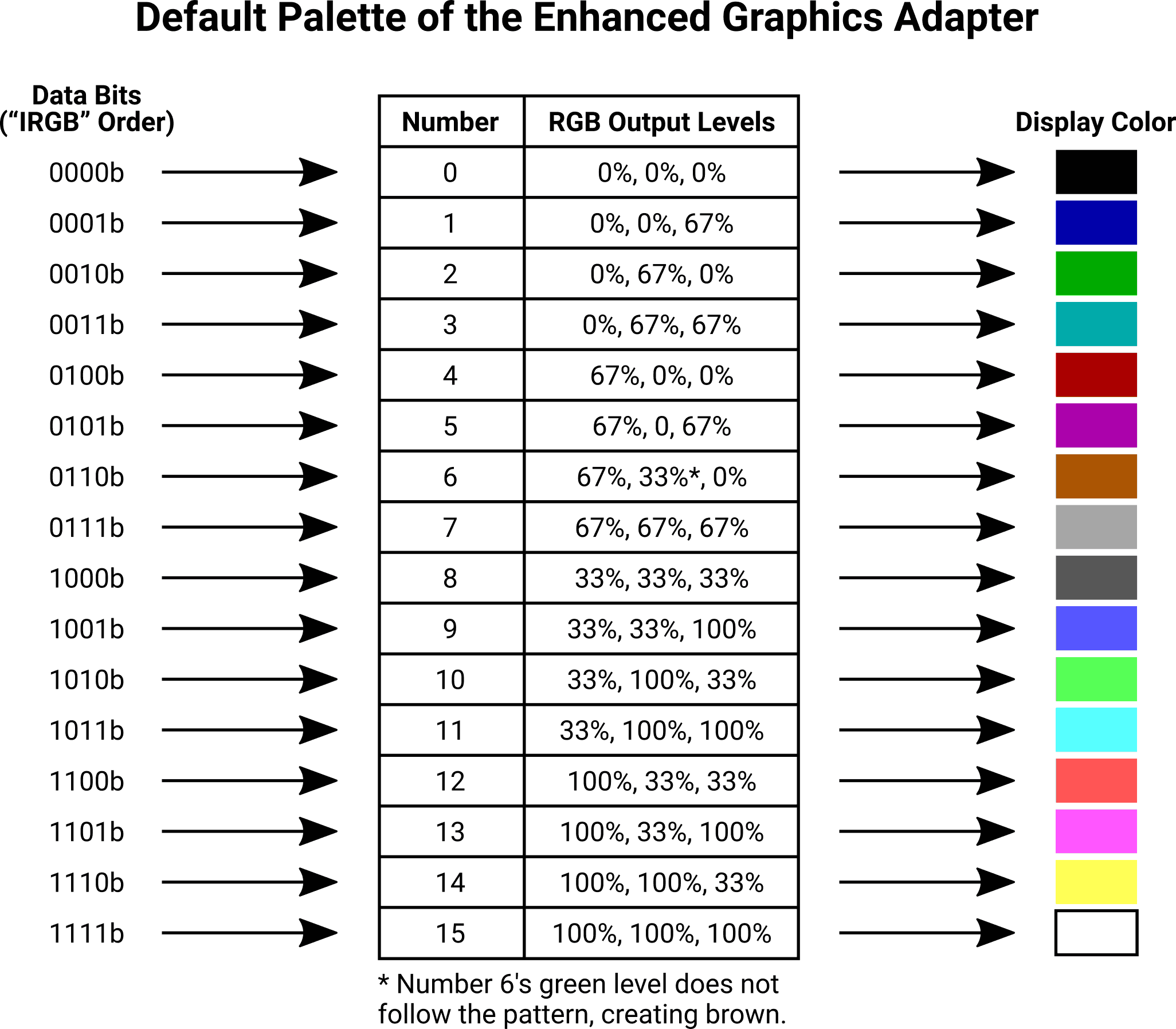
Most software never bothered to actually change anything within the palette, which meant the EGA’s default palette was usually in use. The default palette, to retain color compatibility with the older Color Graphics Adapter (CGA) that preceded it, was arranged so the individual bits in the palette number had a predictable effect on the display color. The four bits were assigned to red, green, blue, and intensity (RGBI). The RGB bits could each be off (output level 0%) or on (output level 67%). If the intensity bit was on, an additional 33% was added to the output levels of all three channels simultaneously:
RGBI bits are not always stored in R-G-B-I order. Sometimes it’s I-R-G-B, B-G-R-I, or really any other permutation that struck the programmer’s fancy.
Exceptions to the Rule
There was a special case embedded in the EGA’s default palette. The color that some may refer to as “dark yellow” (RGBI 1, 1, 0, 0) had its green channel artificially reduced to create more of a pleasing brown shade. This results in brown’s palette entry sort of “breaking” the patterns that the rest of the colors follow.
The CGA used to handle this special case directly in the hardware of the monitor!
Again, it’s important to remember that RGBI is not some absolute truth that’s ingrained in the EGA hardware. It’s simply a palette arrangement that tries to assign intuitive meanings to each individual bit in the palette number. Never assume that just because a file uses 4-bit color, its palette must be RGBI.
Game Palette
As luck would have it, the game does not define any custom palettes. With the exception of the “fade in/out” effect, the menus and full-screen images are all drawn with the default EGA palette. This means that the four palette number bits in the full-screen image files are RGBI, and actually represent (in order) blue, green, red, and intensity.
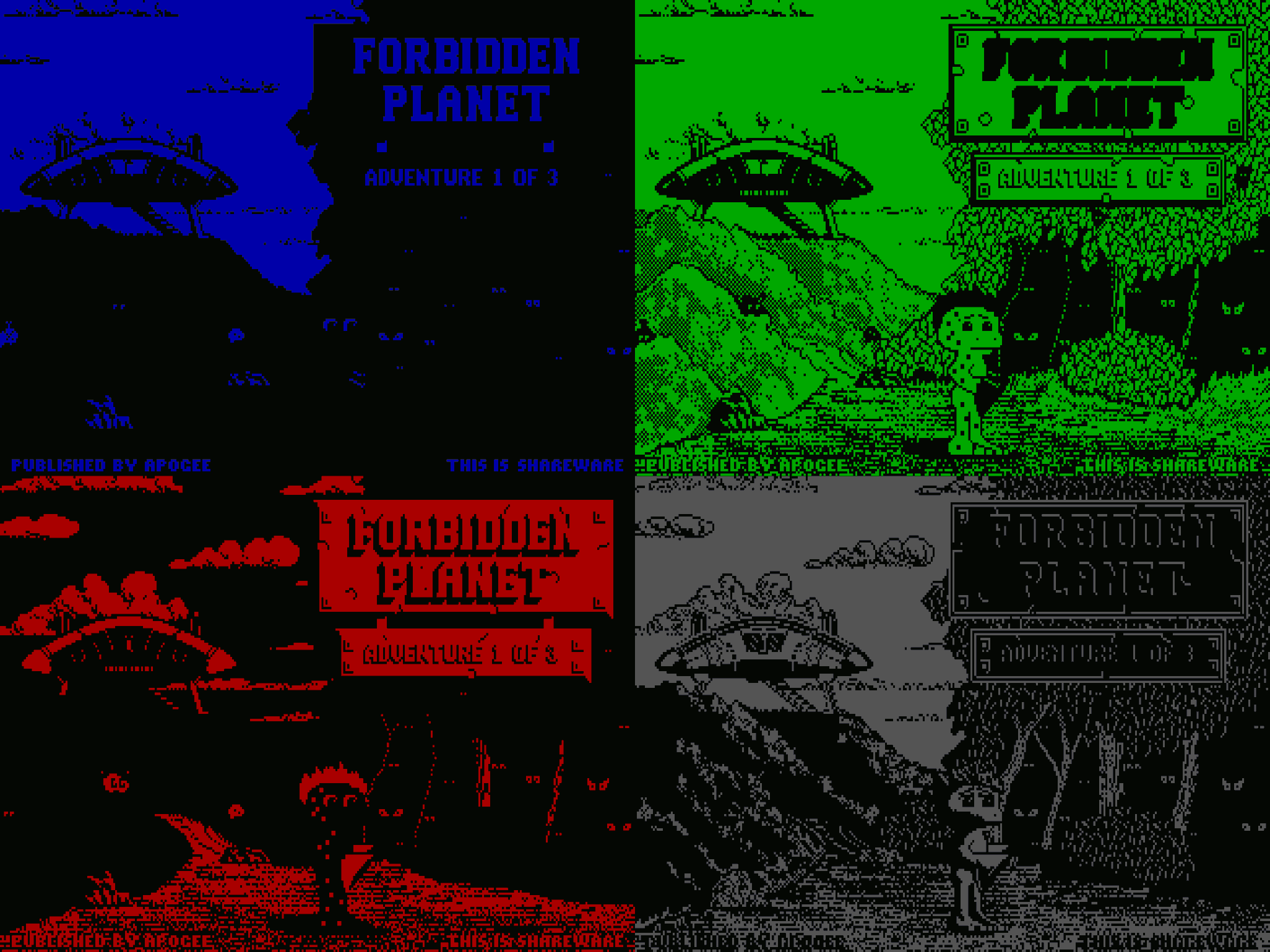
The raw palette bits, colorized to represent what they contribute to the output image, look a bit like low-res Warhol pop art:
Reconstructing the discrete RGBI bits into an RGB color for display takes a small amount of effort, but it can be done without a lookup table thanks to the sensible layout of the default palette:
# rbit/gbit/bbit/ibit are palette bits (0 or 1) from the input data
# r/g/b are output color channel values in the range 0..255
r = (rbit * 0xAA) + (ibit * 0x55)
g = (gbit * 0xAA) + (ibit * 0x55)
b = (bbit * 0xAA) + (ibit * 0x55)

# Correct "dark yellow" to brown
if (rbit, gbit, bbit, ibit) == (1, 1, 0, 0):
    g -= 0x55
Planar Storage
Modern computers and image formats store the RGB elements of a single pixel in close proximity so they can be read, processed, and drawn as a unit. The EGA was rather unusual by comparison, splitting up the image data into four planes with each plane containing one bit position of the palette number.
In full-screen planar image files, each plane occupies 8,000 bytes. Each bit within a plane maps to a unique pixel on the screen, and each byte within a plane controls a span of eight contiguous pixels. So, the first byte of a plane represents screen coordinates (0, 0)–(7, 0), the second byte represents (8, 0)–(15, 0)… Eventually the 8,000th byte of a plane represents (312, 199)–(319, 199). After working through an entire plane, only one bit position at each pixel has been set. The other three planes must then be processed to set the remaining bit positions at each pixel.
To display arbitrary pixels starting at (e.g.) (0, 127), we seek to offset 13D8h (0 + (127 × 320) = 40,640 bits or 5,080 bytes) for the first plane, then repeatedly add 1F40h (8,000 bytes) to that offset in order to access the bits for the remaining planes:
The full-screen planar image format is quite straightforward to parse:
| Offset (Bytes) | Size (Bytes) | Description |
|---|---|---|
| 0 | 8,000 | Plane 0 (blue) pixel data stored as a stream of 64,000 bits, with each bit representing one pixel. Pixel data is stored in row-major order and drawing starts at the top-left corner of the screen. Due to the 320-pixel screen width, each row begins on a 40-byte boundary. |
| 8,000 | 8,000 | Plane 1 (green) pixel data, stored the same way. |
| 16,000 | 8,000 | Plane 2 (red) pixel data, stored the same way. |
| 24,000 | 8,000 | Plane 3 (intensity) pixel data, stored the same way. |


